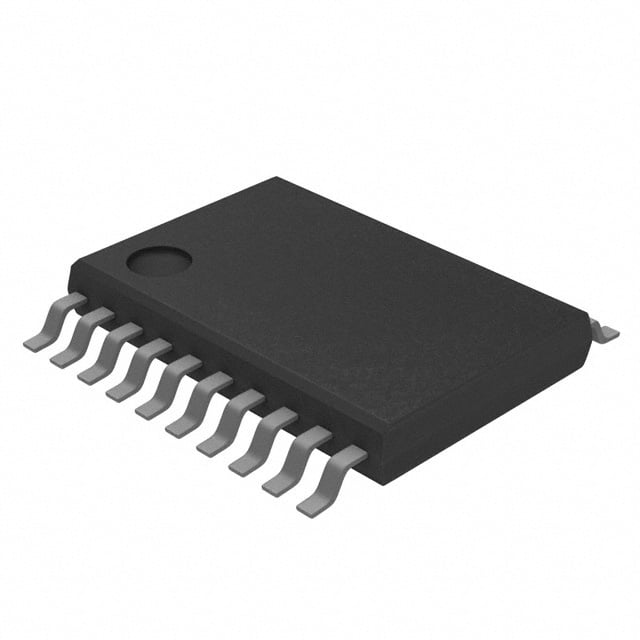
TXS0108EPWR: Datasheet, Pinout and Similar
TXS0108EPWR Introduction
TXS0108EPWR is a bidirectional level converter integrated circuit launched by Texas Instruments. It is widely used in multi-voltage systems for data communication between different voltage domains. The following is a detailed introduction to the chip:
TXS0108EPWR Parameters
TXS0108EPWR Similar Comparison
TXS0108EPWR vs TXB0108PWR vs TXB0106PWR vs TXB0108PWRG4 vs 74LVC8T245PW,118 comparisons
| Parameter | TXS0108EPWR | TXB0108PWR | TXB0106PWR | TXB0108PWRG4 | 74LVC8T245PW,118 |
|---|---|---|---|---|---|
| Image | 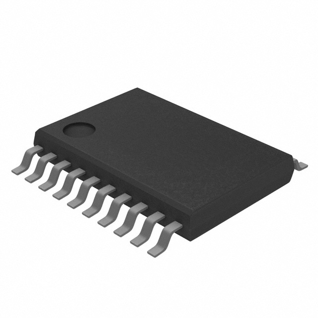 | 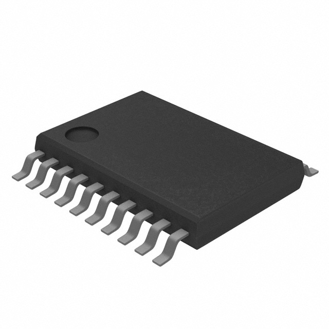 | 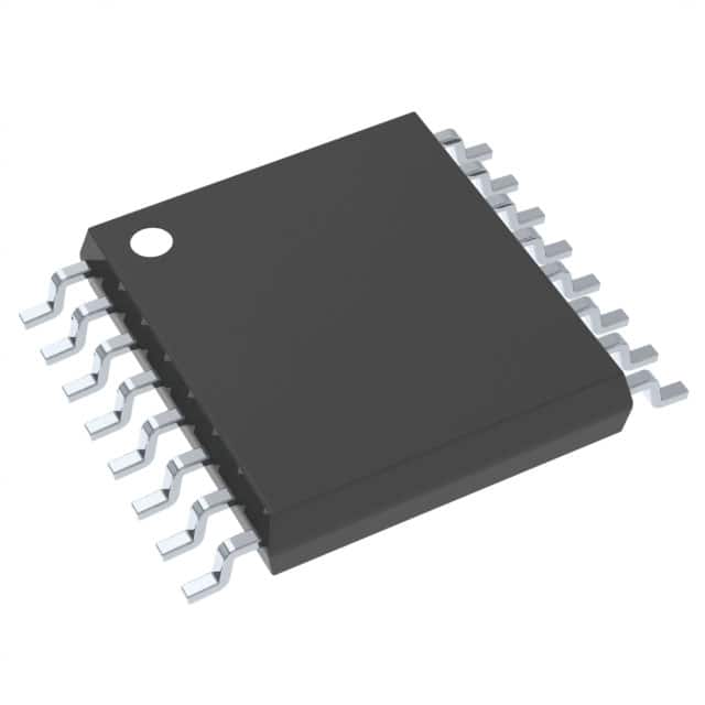 | 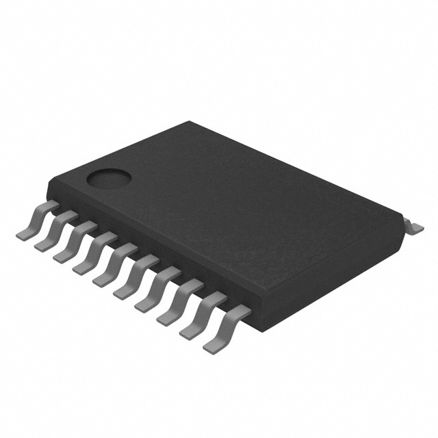 | 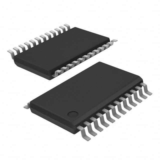 |
| Manufacturer | Texas Instruments | Texas Instruments | Texas Instruments | Texas Instruments | Nexperia USA Inc. |
| Type | Bidirectional Level Shifter | Bidirectional Level Shifter | Bidirectional Level Shifter | Bidirectional Level Shifter | Level Shifter with Direction Pin |
| Voltage Range (VCCA) | 1.2V – 3.6V | 1.2V – 3.6V | 1.2V – 3.6V | 1.2V – 3.6V | 1.2V – 3.6V |
| Voltage Range (VCCB) | 1.65V – 5.5V | 1.8V – 5.5V | 1.8V – 5.5V | 1.8V – 5.5V | 1.2V – 5.5V |
| Direction Control | Auto-detect | Auto-detect | Auto-detect | Auto-detect | Requires Direction Pin |
| Data Rate | 60 Mbps (Push-Pull), 2 Mbps (Open-Drain) | Up to 100 Mbps | Up to 100 Mbps | Up to 100 Mbps | Up to 100 Mbps |
| Channels | 8 | 8 | 6 | 8 | 8 |
| Enable Pin (OE) | Yes | Yes | Yes | Yes | Yes |
| Package | TSSOP-20 | TSSOP-20 | TSSOP-16 | TSSOP-20 | TSSOP-20 |
| Special Features | Pull-up Resistors for Open-Drain Signals | No Pull-up Resistors | No Pull-up Resistors | No Pull-up Resistors | High-Drive Capability |
| Target Applications | I2C, UART, GPIOs | SPI, High-Speed Interfaces | SPI, High-Speed Interfaces | SPI, High-Speed Interfaces | General Multi-Voltage Applications |
Summary of Key Differences
Pull-Up Resistors: TXS0108EPWR includes internal pull-up resistors, making it better suited for open-drain applications like I²C.Other chips (TXB0108PWR, TXB0106PWR, and TXB0108PWRG4) do not have pull-up resistors, focusing on push-pull interfaces like SPI.
Voltage Range: TXS0108EPWR supports a slightly wider range for VCCB (up to 5.5V) compared to TXB0108PWR and others (1.8V to 5.5V).74LVC8T245PW,118 offers the broadest flexibility with VCCA as low as 1.2V and VCCB up to 5.5V.
Direction Control: 74LVC8T245PW,118 requires an explicit direction pin, unlike the other chips which use automatic direction sensing.
Special Applications: For open-drain signaling (e.g., I²C), TXS0108EPWR is the most suitable.For high-speed push-pull signaling (e.g., SPI), TXB0108PWR and its variants are better.
TXS0108EPWR Function
1.Level conversion:
Applicable to convert low voltage signals (such as 1.8V) to high voltage signals (such as 5V) or vice versa.
Can be used as 8-bit unidirectional or bidirectional level converter.
2.Built-in pull-down resistor: Can handle floating input signals and enhance stability.
3.Automatic direction detection:
The data flow direction can be automatically adjusted without additional direction control signals, simplifying circuit design.
4.Support multiple interfaces:
Compatible with LVCMOS and LVTTL standards.
TXS0108EPWR Application Scenarios
1.Communication between multi-voltage processors:
Provide bridging function between 1.8V, 3.3V, and 5V logic level devices.
2.Embedded systems:
For example, connections between microcontrollers (MCUs), single-chip microcomputers (MCUs), FPGAs, and peripheral modules.
3.Portable devices:
Smart phones, tablets, laptops, etc.
4.Level conversion of communication buses such as I²C, SPI, and UART.
TXS0108EPWR pin functions
VCCA and VCCB: Connect low voltage and high voltage power supplies respectively.
OE (output enable):
Control the enable of the level conversion function.
High level enables, low level disables (all I/Os are in high impedance state).
Ax and Bx (x = 1-8):
Bidirectional data channels for signal transmission between low-voltage domain and high-voltage domain.
TXS0108EPWR Datasheet
TXS0108EPWR FAQs
1. What is the main function of TXS0108EPWR?
TXS0108EPWR is an 8-channel bidirectional level translator for logic level conversion between different voltage domains (1.2V–3.6V and 1.65V–5.5V).
It supports automatic direction detection without the need for additional direction control signals.
Built-in pull-up resistors are suitable for handling open-drain communication protocols such as I²C, UART, etc.
2. Does it support high-speed communication?
Yes, TXS0108EPWR supports 60 Mbps data rate (push-pull drive mode) and 2 Mbps (open-drain mode).
It performs well in most embedded system communication scenarios, but is not suitable for applications that require ultra-high-speed (>100 Mbps) data transmission.
3. Do VCCA and VCCB of TXS0108EPWR need to meet a specific relationship?
The power supply voltage range of VCCA and VCCB is:
VCCA: 1.2V–3.6V
VCCB: 1.65V–5.5V
It is necessary to ensure that VCCA ≤ VCCB, otherwise the chip may be damaged or the level conversion may fail.
4. Does TXS0108EPWR require an external pull-up resistor?
The internal pull-up resistor (about 40 kΩ) is integrated, and usually no additional external pull-up resistor is required when processing open-drain signals (such as I²C bus).
If the system requires a higher signal pull-up speed, an external pull-up resistor can be added to optimize performance.
5. How to use the output enable (OE) pin?
The OE pin is used to control the working state of the chip:
High level (logic 1): Enable the level conversion function.
Low level (logic 0): Set all I/O channels to high impedance and stop the level conversion function.
In the design, the OE pin can be connected to VCCA through a pull-up resistor to ensure automatic enable after power-on.
6. Is the TXS0108EPWR suitable for SPI interface?
It is not recommended for SPI interface, especially in high-frequency (>10 MHz) applications, because its built-in pull-up resistor may cause signal integrity issues.
For high-speed SPI communication, it is recommended to use TXB0108PWR or similar level converters, which are designed for push-pull signals.
7. How to avoid common problems when using TXS0108EPWR?
Signal direction issues: Although automatic direction detection is supported, it may fail under certain extreme conditions (such as high bus impedance). Ensure that the signal is clean and has no severe reflections.
Load capacitance: When the load capacitance is too high (such as long cables or large capacitive loads), it may cause a decrease in conversion rate. Try to reduce the line load.
Connection order of VCCA and VCCB: When powering on, it is recommended to stabilize VCCB first, and then power on VCCA.
8. What are the typical application scenarios?
I²C bus communication: achieve logic level matching between masters and slaves with different voltages.
UART serial communication: connect controllers or modules with different voltages.
GPIO expansion: used for signal bridging of different voltage domains in embedded systems.
Low-speed SPI: used for SPI applications with lower data rates (usually <10 Mbps).
9. How to connect the pins of TXS0108EPWR?
Ax: low-voltage side I/O channel, connected to low-voltage domain devices.
Bx: high-voltage side I/O channel, connected to high-voltage domain devices.
VCCA: connected to the power supply of the low-voltage domain.
VCCB: connected to the power supply of the high-voltage domain.
OE: connected to VCCA or control the chip working state through control signals.
10. What are the advantages of TXS0108EPWR compared to TXB0108PWR?
Integrated pull-up resistors: The TXS0108EPWR is better suited for I²C or other open-drain communication protocols, while the TXB0108PWR is better suited for high-speed push-pull communication.
Wider power supply range: The VCCB of the TXS0108EPWR supports up to 5.5V, while the range of the TXB0108PWR is 1.8V–5.5V.
Stronger anti-interference ability: Better adaptability to larger bus impedance or interference environment.
Texas Instruments
In Stock : 12194

