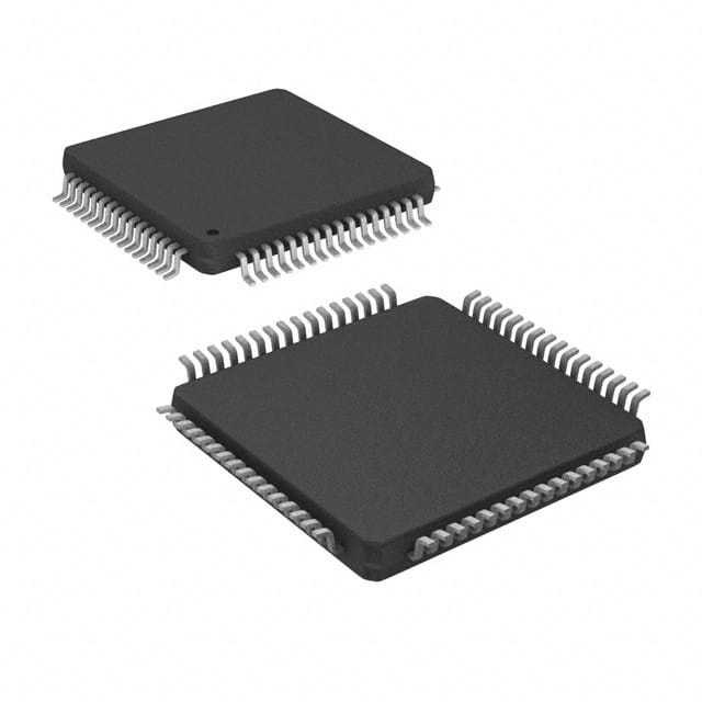
Microchip PIC18 series microcontroller: PIC18F65K80-I/PT
PIC18F65K80-I/PT is an 8-bit microcontroller produced by Microchip, belonging to the PIC18 series, designed for high performance and low power consumption. PIC18F65K80-I/PT is suitable for automotive, building control, elevator control and industrial applications, and can be used as a main control chip to implement various control and data processing tasks.
PIC18F65K80-I/PT Introduction
Basic information
• Core architecture: PIC RISC architecture is adopted, and the data bus width is 8 bits.
• Operating voltage: The operating voltage range is 1.8V to 5.5V, with a wide voltage adaptability, suitable for applications in a variety of different power supply environments.
• Clock frequency: It can work at up to 64MHz, which can meet the processing requirements of higher speed.
Storage system
• Flash memory: It has 32KB of Flash memory, which can be used to store program code and constant data, etc.
• RAM: 3.6KB RAM, used to temporarily store data and intermediate results of program running.
Peripheral interface
• Communication interface: Supports multiple communication interfaces such as CAN, I2C, LIN, SPI, UART/USART, etc., which is convenient for data exchange and communication with other devices.
• Input and output pins: It has 54 programmable I/O pins, which can be flexibly configured as input or output mode according to specific application requirements.
• Timer/Counter: It has 5 timers/counters, which can be used for timing tasks, counting operations, and generating PWM signals.
• Analog-to-digital converter (ADC): It has a built-in 8-bit analog-to-digital converter with 11 channels, which can be used for analog signal acquisition and conversion.
• PWM channel: There are 5 PWM channels, which can be used for applications that require pulse width modulation, such as controlling motors and adjusting light brightness.
Other features
• Low power mode: It has low sleep current and is suitable for application scenarios with high power requirements, such as battery-powered devices.
• Package: 64-pin TQFP package, size 10mm×10mm×1.05mm.
PIC18F65K80-I/PT is suitable for automotive, building control, elevator control and industrial applications. It can be used as a master chip to implement various control and data processing tasks
PIC18F65K80-I/PT Datasheet PDF
PIC18F65K80-I/PT Similar
PIC18F65K80-I/PT vs PIC18F66K80-I/PT vs PIC18F66K80T-I/PT vs PIC18F85K22-I/PT basic parameter comparison
| Parameters | PIC18F65K80-I/PT | PIC18F66K80-I/PT | PIC18F66K80T-I/PT | PIC18F85K22-I/PT |
|---|---|---|---|---|
| Image | 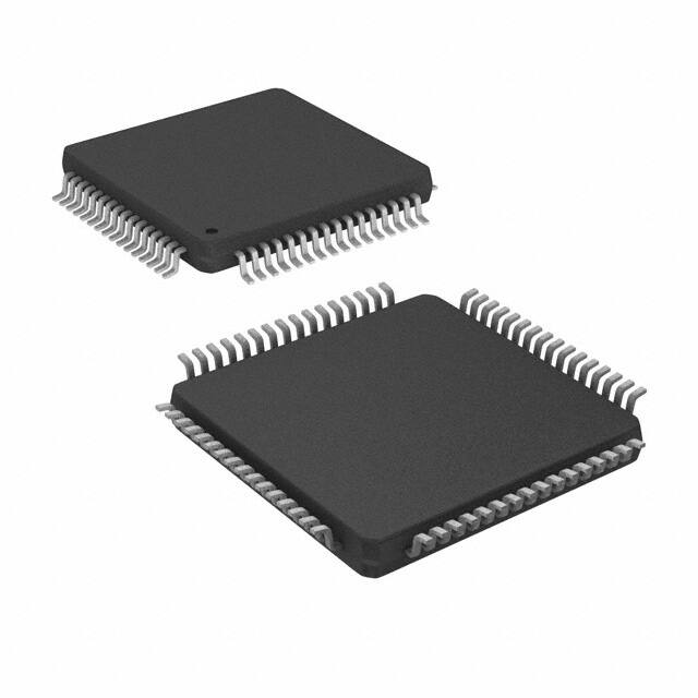 | 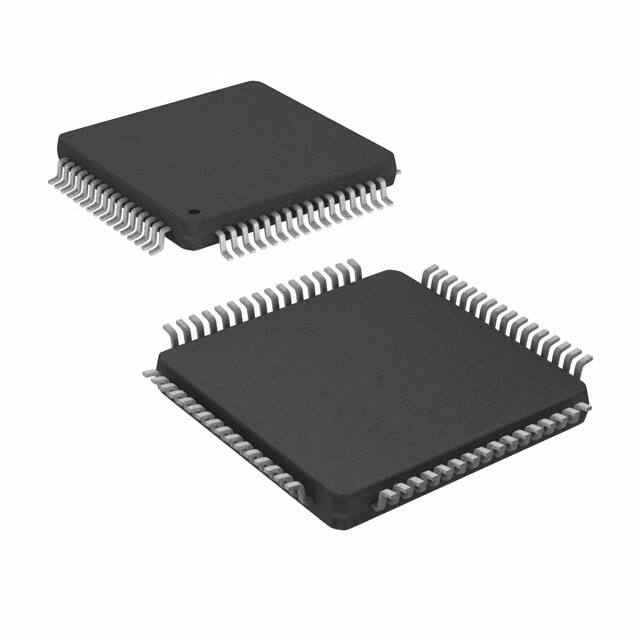 | 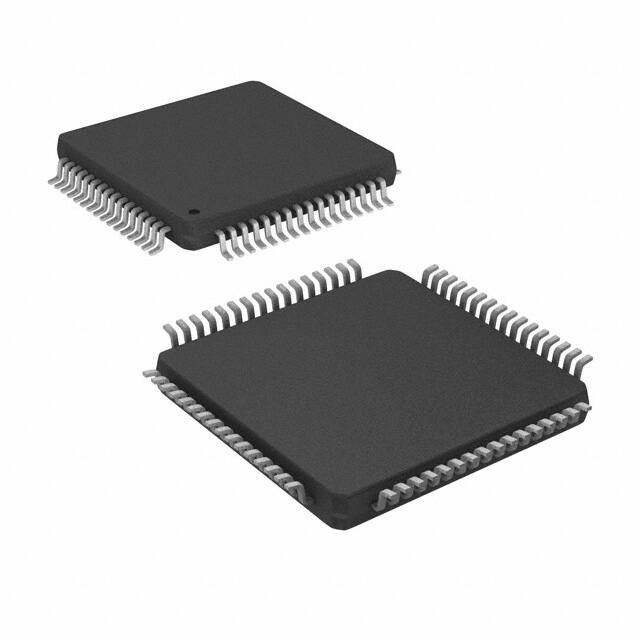 | 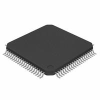 |
| Manufacturer | Microchip Technology | Microchip Technology | Microchip Technology | Microchip Technology |
| Data Bus Width | 8-bit | 8-bit | 8-bit | 8-bit |
| Instruction Set | PIC RISC | PIC RISC | PIC RISC | PIC RISC |
| Operating Voltage (V) | 1.8 - 5.5 | 1.8 - 5.5 | 1.8 - 5.5 | 2.0 - 5.5 |
| Max Clock Frequency (MHz) | 64 | 64 | 64 | 64 |
| Flash Memory (KB) | 32 | 64 | 64 | 32 |
| SRAM (KB) | 3.6 | 4 | 4 | 2 |
| EEPROM (KB) | N/A | N/A | N/A | 256 |
| I/O Pins | 54 | 54 | 54 | 36 |
| Package | 64-pin TQFP | 64-pin TQFP | 64-pin TQFP | 44-pin TQFP |
| ADC Channels | 11 | 12 | 12 | 11 |
| ADC Resolution (bits) | 8 | 8 | 8 | 10 |
| PWM Channels | 5 | 5 | 5 | 2 |
| Communication Interfaces | CAN, I2C, LIN, SPI, UART/USART | CAN, I2C, LIN, SPI, UART/USART | CAN, I2C, LIN, SPI, UART/USART | CAN, I2C, SPI, UART/USART |
| Timer/Counters | 5 | 5 | 5 | 5 |
PIC18F65K80-I/PT FAQ
1. How to program PIC18F65K80-I/PT?
MPLAB X IDE and MPLAB XC8 compiler can be used for programming. Microchip provides comprehensive software support.
It is recommended to use debugging tools such as ICD 4 or PICkit 4 for code download and debugging.
The chip supports standard interfaces such as USB, UART, and I2C, and data can be exchanged through these interfaces.
2. Does PIC18F65K80-I/PT support CAN bus communication?
Yes, PIC18F65K80-I/PT has a built-in CAN controller and supports CAN 2.0A/B protocol, which is suitable for industrial, automotive, communication and other occasions that require high-reliability real-time data exchange.
3. How to configure ADC (analog-to-digital converter)?
PIC18F65K80-I/PT provides 16 channels of 10-bit ADC, supporting single-ended and differential input modes.
Parameters such as ADC clock source, input channel, sampling time, etc. can be configured by programming.
When using MPLAB X IDE, the ADC working mode can be set by configuring registers and functions in the program.
4. Which interfaces are suitable for communicating with external devices?
UART: used for serial communication, commonly used to connect with other microcontrollers or external modules (such as GPS modules).
I2C: used for multi-device communication, suitable for connecting external devices such as sensors and displays.
SPI: high-speed serial communication, often used to connect with high-speed peripherals (such as EEPROM, LCD controller, etc.).
CAN: used for high-reliability communication such as industrial and automotive.
5. How to reduce the power consumption of PIC18F65K80-I/PT?
You can use Sleep and Idle modes to reduce the activity of the processor and extend battery life.
When some peripherals are not in use, turn them off to reduce power consumption.
Configure a suitable clock source to avoid the use of high-frequency clocks.
6. How to use the watchdog timer (WDT)?
The watchdog timer (WDT) is used to monitor whether the system is running normally. If the program hangs, the WDT will reset the system.
You can set the timing period by configuring the WDT register and reset the WDT (i.e. feed the dog) regularly in the program to prevent reset.
7. Does PIC18F65K80-I/PT support external interrupts?
Yes, it supports external interrupts (INT0 and INT1). The trigger mode of external interrupts can be configured (rising edge, falling edge or dual edge) and processed in the interrupt service routine.
The chip also provides multiple internal interrupt sources (such as ADC completion, interrupt priority, etc.).
8. How to choose a suitable power supply?
The PIC18F65K80-I/PT supports a power supply voltage of 2.0V to 5.5V. It is recommended to use a stable DC power supply.
To ensure the normal operation of the chip, it is recommended to provide it with a low-noise power supply and add appropriate decoupling capacitors to stabilize the power supply voltage.
9. How to configure PWM output?
The chip supports multiple PWM outputs, which are suitable for applications such as motor control and brightness adjustment.
The frequency, duty cycle and other parameters of the PWM signal can be configured.
PWM can be configured through dedicated modules (such as CCP or ECCP) or generated by software timers.
10. What tools can be used for debugging?
Use MPLAB X IDE for programming and debugging.
It can be used with PICkit 4 or ICD 4 debuggers for hardware debugging, real-time viewing of registers, memory status, stepping code, etc.
11. Does PIC18F65K80-I/PT support firmware upgrade?
Yes, this microcontroller supports Bootloader function, which can be used to upgrade firmware through communication interfaces such as UART and I2C. Using a dedicated Bootloader program, firmware updates can be performed while the system is running.
Microchip
In Stock : 10254

