Explain clearly the parallel and series connection of capacitors at one time
Parallel capacitors
Parallel capacitors refer to connecting the positive and negative poles of two or more capacitors together to form a new capacitor group. This connection method can increase the total capacitance of the capacitor group and provide greater energy storage capacity and better power supply filtering effect. Here are some details about parallel capacitors:
Basic concepts of parallel capacitors
1. Calculation of total capacitance:
When capacitors are connected in parallel, the total capacitance
Ctotal is the sum of the capacitances of all parallel capacitors:
Ctotal=C1+C2+C3+…+Cn
Where, C1,C2,C3,…,Cn
are the capacitances of each parallel capacitor respectively.
2. The same voltage:
In parallel capacitors, the voltage across all capacitors is the same.
3. Charge distribution:
The total charge in the parallel capacitors
Qtotal is equal to the sum of the charges stored in each capacitor:
Qtotal=Q1+Q2+Q3+…+Qn
Where, Q=C⋅V, that is, the charge of the capacitor is proportional to the product of capacitance and voltage.
Application of parallel capacitors
1. Power supply filtering:
Parallel capacitors are often used in power supply circuits to reduce power supply noise and ripple and improve power supply stability.
2. Improve energy storage capacity:
Parallel capacitors can increase the total capacitance, thereby improving the energy storage capacity of the circuit.
3. Circuit tuning:
In some RF and communication circuits, parallel capacitors can be used for circuit tuning and matching.
Example of capacitors in parallel
Here is a simple example showing how to calculate the total capacitance of capacitors in parallel:
Assuming there are three capacitors with capacitances of
C1=10μF, C2=20μF, C3=30μF, the total capacitance ? total is:
Ctotal=C1+C2+C3=10μF+20μF+30μF=60μF
Illustration of capacitors in parallel
Here is a circuit diagram of capacitors in parallel:
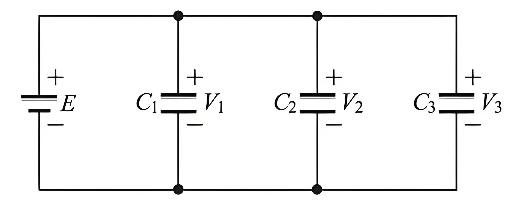
In this circuit, the positive and negative electrodes of capacitors
C1, C2, and C3 are connected together to form a parallel capacitor group.
By connecting capacitors in parallel, the total capacitance can be effectively increased, improving the energy storage capacity and filtering effect of the circuit, which is very common in practical applications.
Series Capacitors
Series capacitors refer to the connection of two or more capacitors end-to-end, forming a capacitor group that results in a lower total capacitance. Unlike parallel capacitors, the total capacitance of series capacitors decreases. Common applications of series capacitors include voltage dividers and high-voltage capacitor applications.
Basic Concept of Series Capacitors
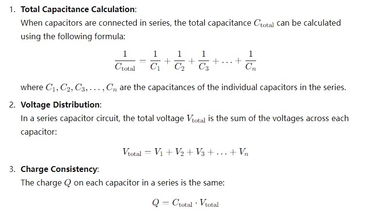
Applications of Series Capacitors
- High-Voltage Applications: In high-voltage applications, series capacitors can share the voltage, reducing the voltage stress on individual capacitors and increasing the voltage handling capability of the capacitor group.
- Voltage Dividers: Series capacitors can be used to construct voltage dividers, which are useful for voltage measurement or signal conditioning.
- Tuning Circuits: Series capacitors are used in tuning circuits to adjust the resonant frequency of the circuit.
Example of Series Capacitors
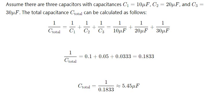
Schematic of Series Capacitors
Below is a schematic diagram of series capacitors:
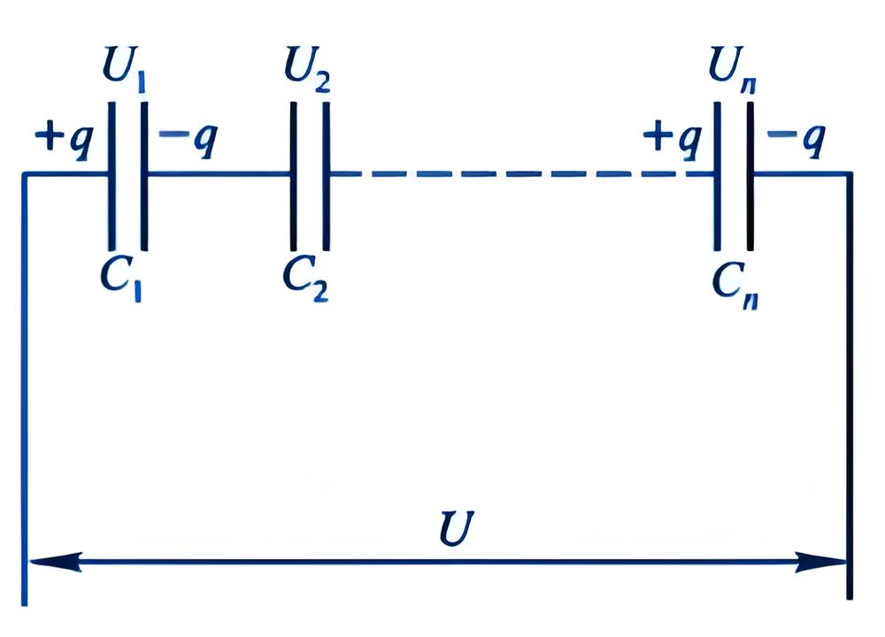
In this circuit, the capacitors C1, C2, and C3 are connected end-to-end, forming a series capacitor group.
By connecting capacitors in series, one can achieve voltage division and increase the voltage handling capability of the circuit, which is useful in specific circuit designs.
What are the classifications of capacitors we commonly use?
Aluminum polymer capacitors, such as: 6SVPE220MW from Panasonic
Aluminum electrolytic capacitors, such as: EEVFK2A331M from Panasonic
Ceramic capacitors, such as: VJ0805D390JEAAR from Vishay Intertechnology
Thin film heaters, such as: 02013J1R9PBSTR from Kyocera AVX
Silicon capacitors, such as: RFCS04026000DBTT1 from Vishay Intertechnology
Double-layer capacitors, such as: MAL219690116E3 from Vishay Intertechnology, DGH107Q2R7 from Cornell Dubilier

