CAN/LIN communication matrix headlight solution based on Microchip PIC16F1779 onsemi NCV78343 and OSRAM LED
For LED intelligent lighting solutions, Microchip's MCU integrates peripheral modules independent of the core to implement switch power control, logic control and communication functions. Compared with pure analog or ASIC implementation solutions, it can significantly improve flexibility. This solution adds the ON Semiconductor NCV78343 matrix control chip to realize the CAN/LIN communication matrix headlight solution.
PIC16F1779 can independently control up to four LED channels, which is a unique capability that most off-the-shelf LED driver controllers do not have, and is particularly suitable for the design of combined headlights/taillights.
The LED dimming engine consists of analog peripherals integrated in the microcontroller, which are connected through MCC configuration to form four independent LED dimming drivers. Once configured, the switch-mode power converter can be controlled automatically with almost no central processing unit (CPU) intervention. This frees up the CPU to perform other important tasks, such as monitoring functions, communication functions or newly added intelligent functions in the system. Parameters such as output voltage and current can also be changed in real time through the MCU.
1. Universal four-channel LED driver solution:
A four-way LED dimming engine is integrated on a single MCU, which can realize up to four completely independent LED string constant current drives, using a SEPIC buck-boost topology structure, with a wider range of applications. For different LED loads, you only need to adjust the output voltage and current in the software. The daytime running lights and position lights share the third channel, time-division multiplexing, and software dimming.
2. High-performance LED dimming engine:
High-resolution dimming PWM is used to achieve continuous and smooth brightness adjustment, and synchronous load switches are used to avoid color temperature drift.
3. Digital frequency jitter:
Frequency jitter can be used to optimize EMC characteristics and disperse the EMI emission energy generated during switching to other frequencies, thereby reducing EMI. Digital frequency jitter can be implemented in software, which is flexible and does not increase hardware costs.
4. Adjustable PWM frequency:
The PWM frequency can be adjusted to select the appropriate switching frequency to optimize the conversion efficiency and avoid certain EMI frequencies.
5. Support CAN/LIN communication:
Use Microchip MCP25625T-E/MLVAO integrated CAN controller and transceiver chip to expand CAN communication function. Use Microchip LIN SBC ATA663254-GAQW integrated LDO and LIN transceiver chip to expand LIN communication function.
6. Hardware overvoltage protection:
Use the MCU's internal DAC, comparator and COG complementary waveform generator to achieve configurable hardware overvoltage protection. When the output voltage exceeds the set voltage, the comparator will directly turn off the COG output to achieve hardware-level overvoltage protection without MCU intervention, zero-delay response, to ensure that the LED will not be damaged by overvoltage.
7. Undervoltage/overvoltage warning, over-temperature protection:
By AD sampling to detect the output voltage, PCB and LED temperature, undervoltage/overvoltage/over-temperature protection is achieved, and the output brightness can be flexibly adjusted.
8. Soft start function:
Soft start function can be realized through software to avoid overvoltage/overcurrent when LED is turned on, and also avoid impact on input power supply.
9. Matrix control function:
Using onsemi NCV78343DQ0R2G with four-way SEPIC buck-boost constant current source to realize four-way matrix control, various animation effects and matrix control can be realized.
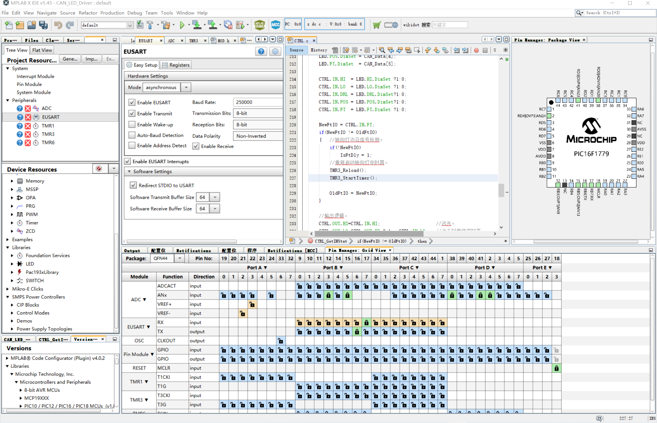
10. MPLAB X IDE graphical configuration:
Use MPLAB X IDE MCC plug-in graphical configuration to generate initialization code and underlying drivers for various peripheral modules, which greatly simplifies the difficulty of software development, and development can be completed almost without looking at registers.
11. Provide SDK development kit and sample source code:
The carefully designed SAC_CAN_LED_Lib SDK development kit has helped you build four-way PCMC constant voltage/constant current drive, PWM dimming, MCP25625 CAN drive, USART drive, frequency jitter and other functions, and provides API interface for you to call.
Software development environment, supports MPLAB X IDE MCC graphical configuration
Solution Introduction
Key Materials List of Solutions (All the following devices are automotive grade)
| No. | Brand | Original complete part number | Category 1_MCU / Connectivity / Sensor |
|---|---|---|---|
| 1 | Microchip | PIC16F1779T-E/MLVAO | MCU with CIP |
| 2 | Microchip | MCP1416T-E/OTVAO | MOS Driver |
| 3 | Microchip | MCP16311T-E/MSVAO | DC-DC |
| 4 | Microchip | ATA663254-GAQW-VAO | LIN SBC |
| 5 | Microchip | ATA6561-GAQW | CAN Transceive |
| 6 | Microchip | MCP25625T-E/MLVAO | SPI CAN Controller + Transceiver |
| 7 | Microchip | PIC18F25K83-I/SSVAO | CAN MCU |
| 8 | onsemi | NCV78343DQ0R2G | Series String Pixel Controller |
| 9 | onsemi | NVMFS5C682NL | MOSFET |
| 10 | OSRAM | KW CELMM1.TG | LED |
| 11 | Nexperia | PMEG100V100ELPD | Diode |
| 12 | CHILISIN | APCI00121280150MB2 | Coupled inductor |
Specifications
| PWM frequency: | 333KHz (250KHz~500KHz software adjustable) |
| Conversion efficiency: | 82%~85% |
| Over-temperature protection: | Above 112.5℃, derate to 80%, above 122.5℃, derate to 70%. (Software adjustable) |
| LED fault detection: | Support |
| LIN communication: | Support (use MCC to generate code) |
| CAN communication: | Support (driver API is provided in SDK), support control, status, and fault feedback. |
| Switch control: | Support |
| Digital frequency jitter: | Support (software adjustable) |
| Soft start: | Support (software adjustable) |
| Input anti-reverse connection: | Support |
| Current resolution: | 6.66666667mA (related to the value of the LED current sampling resistor, large resistance, high resolution) |
| Maximum power: | 40W x 4 channels |
| Input voltage: | DC 9V~24V |
| Matrix control: | NCV78343 maximum 1.5A*12 LEDs*4 channels |
| Animation effect: | Startup animation, shutdown animation |
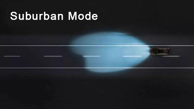
Scene application diagram

Display board photo

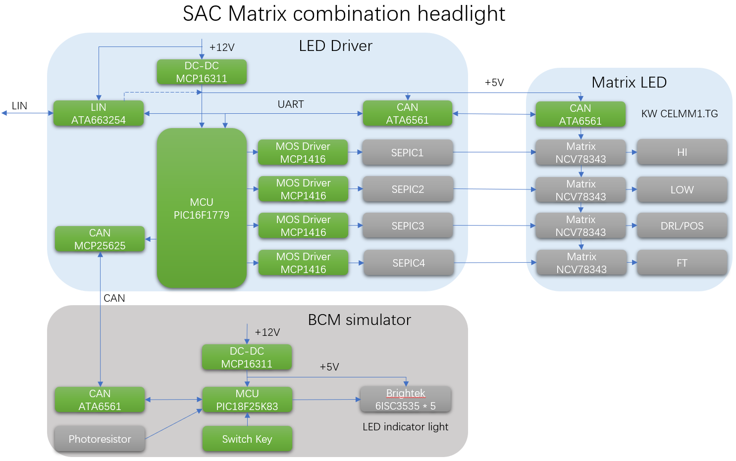
Solution block diagram
City mode

Suburban mode
Highway mode

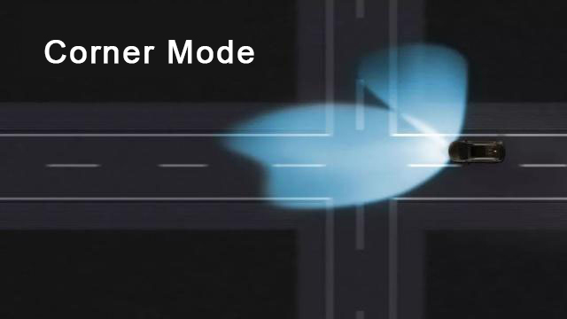
Curner mode
Intelligent high beam mode

Core technology advantages
[Technical advantages
1. PIC16F1779 single hybrid power MCU (built-in PRG slope compensation, OPA op amp, COMP comparator, COG complementary waveform generator, DAC, ADC, USART and other peripherals) realizes four-way SEPIC buck-boost constant current drive, CAN/LIN protocol processing, and matrix chip animation control.
2. PCMC peak current mode is used to quickly respond to load changes, SEPIC topology is used to achieve buck-boost, single-channel constant current can reach 1A (pay attention to LED heat dissipation), and PWM dimming is supported.
3. Hardware-level overvoltage protection, automatically shut down PWM output when overvoltage occurs.
4. By detecting the terminal voltage of the LED string, LED open circuit, short circuit and other faults can be judged, and the feedback is sent to the BCM simulator through CAN communication to display on the indicator light.
5. NTC thermistor detects LED temperature to achieve overheating protection and over-temperature derating operation.
6. Photoresistor is used to detect the ambient light intensity to achieve automatic headlight function.
7. Simulate BCM to send CAN commands to control the headlight on/off, dimming, switch animation, matrix control, reset, voltage/status/fault feedback.
8. Four-way drive to realize combined headlight function, including high beam, low beam, daytime running light, position light, turn signal light. (Daytime running light and position light share the third drive, and the brightness is adjusted through software).
9. NCV78343 UART Over CAN communication, which can support long-distance transmission. Automatic addressing at startup, 4 cascades to realize independent control of 48 (12*4) LEDs.
10. Modular design, easy to modify and replace modules to match different functional requirements.
11. Support MPLAB X IDE MCC graphical code configuration plug-in, graphically generate low-level drivers, and develop quickly.
12. The carefully designed SAC_CAN_LED_Lib SDK development package has helped you build four-way PCMC constant voltage/constant current drive, PWM dimming, MCP25625 CAN drive, USART drive, frequency jitter and other functions, and provides API interfaces for you to call.
13. After signing the NDA, schematics, PCB drawings, bill of materials, software example source code, SDK development package, and CAN communication protocol can be provided.
Solution Specifications
PWM frequency: 333KHz (250KHz~500KHz software adjustable)
Conversion efficiency: 82%~85%
Over-temperature protection: above 112.5℃, derate to 80%, above 122.5℃, derate to 70%. (Software adjustable)
LED fault detection: Supported
LIN communication: Supported (use MCC to generate code)
CAN communication: Supported (driver API is provided in SDK), support control, status, and fault feedback.
Switch control: Support
Digital frequency jitter: Support (software adjustable)
Soft start: Support (software adjustable)
Input anti-reverse connection: Support
Current resolution: 6.66666667mA (related to the value of the LED current sampling resistor, the larger the resistance, the higher the resolution)
Maximum power: 40W x 4 channels
Input voltage: DC 9V~24V
Matrix control: NCV78343 Maximum 1.5A*12 LEDs*4 channels
Animation effect: Startup animation, shutdown animation.

