What is a clamping diode? Principle, function and application analysis
Understanding Clamping Diodes
Clamping diodes, also known as protection diodes, are crucial components in electronics, offering protection and voltage control in circuits. They possess unique voltage response characteristics, which make them essential for limiting voltage levels and safeguarding circuit components. Typically made from materials like silicon, germanium, or silicon carbide, clamping diodes provide high-speed response and minimal leakage current.
Working Principle of Clamping Diodes
Clamping diodes operate by conducting current when a specific voltage threshold is exceeded.
- Negative Terminal Grounded:If the positive terminal's voltage rises above ground, the diode conducts, clamping the voltage to nearly zero or slightly below (disregarding the diode's forward voltage drop).
- Positive Terminal Grounded:When the voltage at the negative terminal rises above ground, the diode remains off, leaving the circuit unaffected by the diode's operation.
The critical voltage level at which the diode begins conducting is known as the clamp voltage, serving as the control point for voltage limitation.
Functions of Clamping Diodes
- Voltage Limiting:Clamping diodes restrict the voltage within a circuit to a predefined range, protecting components from excessive voltage levels.
- Circuit Protection:When voltages exceed safe operating levels, the diode conducts, redirecting excess voltage to ground or a safe pathway, thereby safeguarding sensitive components.
- Waveform Shaping:In signal processing, clamping diodes help maintain a desired waveform by eliminating voltage spikes or distortions.
- Voltage Stabilization:These diodes can assist in voltage regulation, ensuring consistent operation of the circuit by maintaining stable voltage levels.
Types of Clamping Diode Circuits
According to the circuit structure, the clamp diode has two circuit modes, one is a simple type and one is a bias type.
Simple positive clamp circuit
Circuit principle: When the input Vin is negative half a week (Vin is negative and positive), the diode is switched on, the current is shown as the red arrow, the capacitor is charged to V (left negative and right positive), Vout=0V; When the input Vin is in positive half cycle (Vin is positive and negative on the bottom), the diode is cut off, the current is shown as the blue arrow, Vout voltage is equal to the capacitor voltage plus positive half cycle voltage, so Vout=2V;

Simple positive clamp circuit
Simple negative clamp circuit
Circuit principle: Input Vin in positive half week (Vin is positive and negative), diode conduction, current as shown by the red arrow, capacitor at both ends of the differential pressure charge to V (left positive and right negative), Vout=0V;
When the input Vin is negative half cycle (Vin is negative and positive on the bottom), the diode is cut off, the current is shown as the blue arrow, and the Vout voltage is equal to negative (capacitor voltage negative half cycle voltage), that is, Vout=-2V;

Simple negative clamp circuit
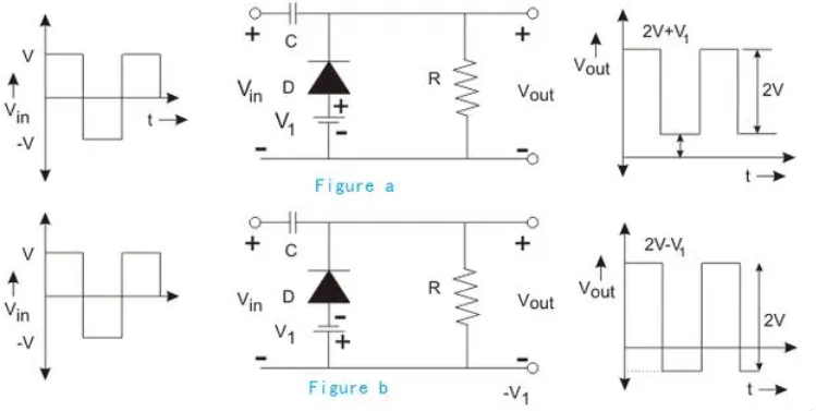
Bias type positive clamp circuit
A bias clamp circuit is similar to a limiter circuit in that a bias voltage is added to the circuit to raise or lower the clamp value.
Figure a shows the forward bias type. When the bias applied is consistent with the diode conduction direction, the waveform is upward, that is, the clamp value will increase V1.
Figure b shows the reverse bias type. When the bias applied is opposite to the diode conduction direction, the waveform is downward, that is, the clamp value will decrease V1.

Bias type positive clamp circuit
Bias type negative clamp circuit
A biased negative clamp is similar to a biased positive clamp in that a bias voltage is added to the circuit to raise or lower the clamp value.
Figure C shows the reverse bias type. When the bias applied is opposite to the diode conduction direction, the waveform is upward, that is, the clamp value will increase V1.
Figure D shows the forward bias type. When the bias applied is the same as the diode conduction direction, the waveform is downward, that is, the clamp value will decrease V1.
ALSO READ: Exploring the Zener Diode| Definition, Uses & Fuctions
Applications of Clamping Diodes
- Signal Limiting:Clamping diodes act as signal limiters in communication systems, ensuring signal amplitudes remain within a safe range to protect receivers.
- Voltage Regulation:Used in power supplies, clamping diodes stabilize input voltage fluctuations, providing steady voltage for sensitive devices like computers and measuring instruments.
- Temperature Compensation:Due to their temperature-dependent forward voltage drop, clamping diodes can be paired with thermistors for temperature stabilization.
- Waveform Correction:In analog circuits, these diodes can eliminate noise and distortions from input signals, improving waveform stability.
- Voltage Detection:Clamping diodes are used in voltage detectors to monitor and respond to specific voltage thresholds, triggering alerts or circuit actions.
Clamping Diodes vs. Zener Diodes
- Clamping Diodes: Limit voltage to protect circuits by conducting during overvoltage events.
- Zener Diodes: Primarily used for voltage regulation, maintaining a steady reverse breakdown voltage.
In comparator designs, clamping diodes limit the output voltage range, ensuring it stays within safe boundaries and protClamping Diodes in Comparator Circuitsecting subsequent components.
FAQs About Clamping Diodes
1.Q:What is the primary role of a clamping diode?
A:Clamping diodes limit voltage to safeguard circuits from spikes, transient surges, and other overvoltage events.
2.Q:How do clamping diodes differ from Zener diodes?
A:Zener diodes regulate voltage in reverse bias, while clamping diodes prevent overvoltage in either direction.
3.Q:Why are clamping diodes used in signal circuits?
A:Clamping diodes stabilize signal amplitudes and prevent voltage spikes, ensuring reliable circuit performance.
