USB Type-C standard data and power configuration method
Data transmission:


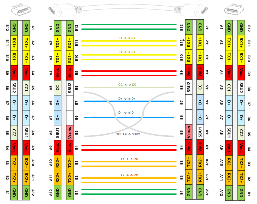
Figure 1: Untwisted, unflipped direct connection
Figure 1 shows the connection state when the cable is not twisted and the socket is not flipped. From the left socket to the right socket, the RX1 line pair is connected to the TX1 line pair, the RX2 line pair is connected to the TX2 line pair; D+ is connected to D+, D- is connected to D-, SBU1 is connected to SBU2, and CC1 is connected to CC1 via the CC line.
USB 3.1 only needs to use two pairs of data lines. In this case, high-speed data is transmitted from one end to the other via RX1+/- and TX1+/-.
The VCONN at both ends of the cable does not need to be connected. The VCONN that powers the electronic tag IC in the cable comes from one end of the cable, and it is provided when the electronic tag chip is determined to be present in the cable.


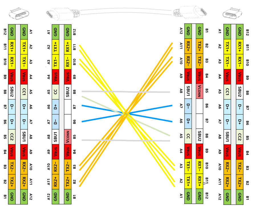
Figure 2: Connection after the cable is twisted
The connection state after the cable is twisted without changing the socket position is shown in Figure 2.
In this case, from the left receptacle to the right receptacle, the RX1 pair is connected to the TX2 pair, the RX2 pair is connected to the TX1 pair, D+ is still connected to D+, D- is still connected to D-, SBU1 is connected to SBU1, SBU2 is connected to SBU2, and CC1 is connected to CC2 via the CC line. Now, high-speed data is transmitted from the left RX1+/- and TX1+/- to the right RX2+/- and TX2+/-.
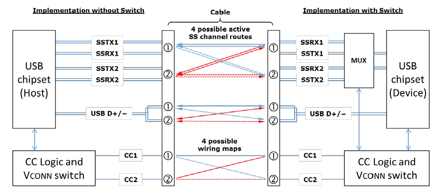
There are 4 possible connection methods in total: the receptacle is flipped or not flipped, the cable is twisted or not twisted.
In the USB 3.1 system, the RX/TX data line needs to use a multiplexer to configure the connection state of the RX/TX line for various possible cable connection states so that the correct communication connection can be formed. Figure 3 shows the routing possibilities of the data lines between USB Type-C ports. The direction of the cable and the receptacle can be understood by measuring the state of CC1/2 on each terminal, and the CC logic controller can complete the routing configuration of the multiplexer accordingly. This work can be done in the multiplexer or in the USB chipset.


USB Type-C interface has a unique reversible pluggable design with 24 pins inside, defining a variety of signal and power lines. When device A and device B are connected via a USB Type-C cable, the first connection is at the physical level, with the pins docking with each other to build a basic channel for subsequent data and power transmission.
The CC (Configuration Channel) pin in the USB Type-C interface is used to detect the connection status and device role. When a device is plugged in, the CC pin sends and receives specific signals to determine whether there is a device connected and the type of connected device, such as host, slave, or dual-role device.
